B Mode Ultrasound Diagram

1 Real Time B Mode Ultrasound Imaging System Download

Imaging Flow Of The Standard B Mode Ultrasound Imaging Prf

Block Diagram Of Ultrasonic Convex B Mode System Showing The
Illustration Of Ultrasound Rf To B Mode Data Conversion Process

Principle Of B Mode Udt Collection A Line Signal Generated By

1 Ultrasound Imaging Modes A Schematic Of The Orientations Of

The histologic features were correlated with the 13 weeks ultrasound findings.
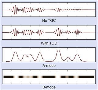
B mode ultrasound diagram. This is the most intuitive of all modes to understand. Usually 100 to 200 or more separate ultrasound beam lines are used to construct each image. Ultrasound beam is swept. Let us consider a linear array probe as described in chapter 3 where the image is formed as illustrated in figure 1 3.
Here the transducer is scanned back and forth to create a 2 dimensional view. A normal mode occurs when all parts of a system oscillate with the same frequency. In its simplest form it appears as bright spots with varying intensity depending on the amplitude as in the diagram. 1 introduction to b mode imaging 3 the pulse echo sequence described above resulted in the display of one line of information on the b mode image.
B scan mode is called so because here the stronger echoes are marked with greater brightness. Medical ultrasound also known as diagnostic sonography or ultrasonography is a diagnostic imaging technique or therapeutic application of ultrasound it is used to create an image of internal body structures such as tendons muscles joints blood vessels and internal organs its aim is often to find a source of a disease or to exclude pathology the practice of examining pregnant women using. Doppler imaging can be used to measure wall and valve motion and to assess blood flow through. This is the default mode that comes on when any ultrasound echo machine is turned on.
B at each time point 4 6 b mode hepatic ultrasound images were acquired in standard imaging. Der grauwert eines bildpunktes auf dem bildschirm ist ein maß für die amplitude. Doppler imaging uses the frequency shift in the received signal to estimate the velocity of ultrasound scatterers. Most ultrasound systems have controls that allow the operator to vary the beam line density either directly or indirectly when some other image processing control is manipulated.
It is a 2 dimensional cross sectional view of the underlying structures and is made up of numerous b mode brightness mode scan lines. The different types of modes can be controlled by the. B mode b für englisch brightness modulation ist eine andere darstellung der information des amplituden modus bei der die echointensität in eine helligkeit umgesetzt wird. The field of view is the portion of the organs or tissues that are intersected by the scanning plane.
M mode images can be used to track myocardial wall and valve motion. The image becomes two dimensional by virtue of the use of an array of multiple transducer. A b m a mode is an operational state that a system has been switched to. Durch mechanisches bewegen der sonde überstreicht der messstrahl eine fläche in einer ebene ungefähr senkrecht zur körperoberfläche.
B mode hepatic ultrasound were made at 0 baseline 10 and 13 weeks after which the rats were euthanized and liver samples were submitted for histologic examination. The b mode display on the monitor follows the axis of the ultrasound beam as it is swept across the imaged region. Here sweeping a narrow ultrasound beam through the transmitting pulses and detecting echoes along closely spaced scan lines produces the b scan images. As with b mode pixel intensities in the m mode image are proportional to the strength of the received echo signal.
For ultrasound imaging different modes are used to examine the arterial venous system heart pancreas urinary system ovaries spinal cord joints and more. During the first.
B Mode Imaging Fujifilm Visualsonics
Physics And Instrumentation In Doppler And B Mode Ultrasonography

Ultrasound Scan Modes Electronics And Communication Study Materials

The Example Of B Mode Ultrasound Scan Report There Are Such As

Tsukuba Elasticity Score Tes Schematic View Sonoelastography
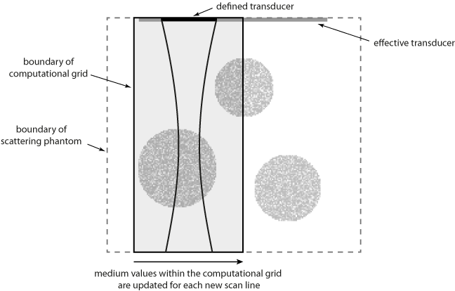
K Wave Matlab Toolbox

A Duplex Ultrasound Output Displaying The B Mode And Colour Flow

B Mode Ultrasound Image Of A Trigger Point Located In The

